
This library ONLY works with AnyLogic 8.8.5 up to 8.9.2. If you are using a different version, you will not be able to use this library. A bug in 8.9.3 doesn’t allow the display of 3D objects from libraries. This hopefully will resolved in future versions.
You can download the library here:
If this library was useful to you, consider donating so we can keep developing this and more in the future, click the following link to donate.
https://www.paypal.com/donate/?hosted_button_id=GW77FD5WVVAR8
Robotic Arm Help Documentation
You can find a video version of this documentation, for version 1.0.0 in the following video:
Important Disclaimer
This robotic arm can be used freely by anyone as long as it’s useful to their case. Nevertheless we DO NOT offer free support for bug correction or implementation of new features. This robotic arm was developed for our own purposes and if it works for you great, otherwise we don’t become suddenly responsible for your project. We also don’t offer free customer support on how to use it, but if you have a doubt that is not explained on this document, we will add it as soon as we can.
If you want new features, we can develop that for a cost. Contact us for this.
If you want personal AnyLogic training and personalized help implementing this for your application, this will also have a cost. Contact us for this, but this documentation should be enough.
General description
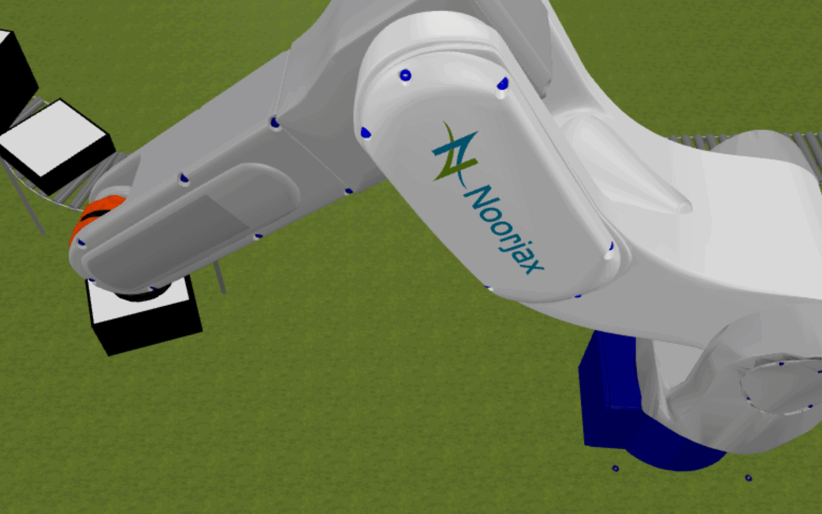
The Robotic Arm library offers tools to model and simulate the dynamics and functionalities of robotic arms used in the manufacturing industry.
It consists of two agents, plus a help agent, which is just a button that will lead you to this page:
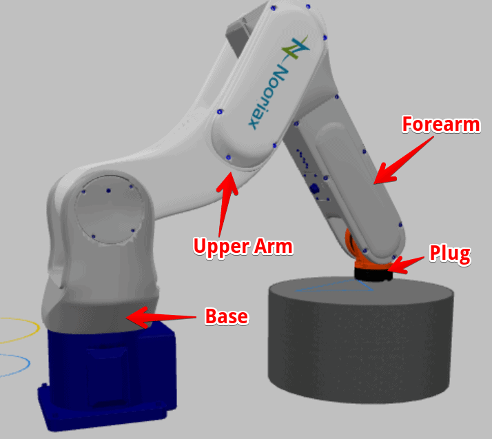
- Robot: represents the 3D animation of the robot. The robotic arm consists of
- A base that rotates in the Z axis
- An upper arm that rotates with respect to the base
- A forearm that rotates with respect to the upper arm.
- A plug that rotates the picked agent to position it correctly on the destination.
- Move By Robot: It’s the flowchart block to be used in conjunction with the Robot agent. It allows defining the logical movements and tasks that the robot will perform for the processed agent.
Other objects that you will see in the library must not be used.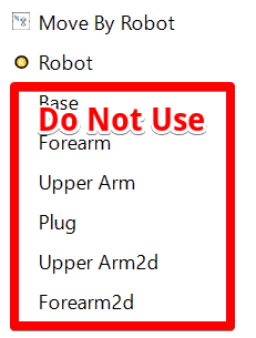
How to Install the Library
First download the library (see head of this documentation) and save it somewhere safe:
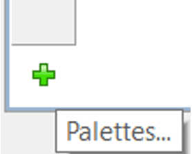
Inside Anylogic, add the library to your palette using the + button on the palette tab, and find the .jar file you downloaded… Always keep that .jar file in the same location, or you will run into issues.
How To Use The Library Once Installed
- To use the robot object, drag and drop the “Robot” object to your workspace (main or any other agent in which your robotic arm will live).
- To use the “Move By Robot” object, you can also drag and drop it, and connect this block with your process logic.
The Robot Object
We define the robot icon, as the agent that represents the physical robot:
We define the robot presentation, as the physical presentation of the robot
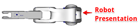
The robot presentation size is by default calculated automatically based on the scale of the agent in which the robot presentation is located. The following are the original measurements, but they can be changed as explained later.
- base length: 3.3 meters, corresponding to the distance from the floor to the upper arm rotation point.
- upper arm length: 3.9 meters, corresponding to the distance between both rotation points
- forearm length: 3.8 meters, corresponding to the distance between the rotation point and the plug.
The Robot Icon
To define the characteristics of the robot, click on the “Robot” icon on your workspace and configure the parameters according to the desired visualization of the robot (make sure that the robot presentation is shown, if not, click on “show the presentation” in the advanced section of the robot icon properties). Also this agent must always be used as a single agent and not as a population of agents (AnyLogic doesn’t allow us to remove this option).
Initial Angles
- Initial base angle (degrees). It’s the initial angle of the base in the Z axis
- Initial upperarm angle (degrees). Initial angle of the upper arm. Zero means no flexion of the joint.
- Initial forearm angle (degrees). This rotation is relative to the upper arm. Zero degrees means no flexion of the joint.
- Recommended joint initial angles (make sure you work within these boundaries in order to avoid the robotic arm to move erratically such as moving into itself… we don’t have collision detection):
- Base angle: any angle between -180 to 180 degrees.
- UpperArm: any angle between -180 to 180 degrees.
- Forearm: any angle between 0 to 180 degrees.
Stats
- Time step (seconds): this defines how often the animation positions are updated. High time step makes the simulation run faster, at the cost of making the animation look weird.
Speed
- Base rotation speed (degrees/second): speed rotation of base in the z axis.
- Forearm rotation speed (degrees/second): speed rotation of forearm relative to the upperarm
- Upperarm rotation speed (degrees/second): self explanatory
Scale
- Additional Scale: this can be used if you want to change the dimensions of the robot. Unfortunately, AnyLogic makes this a bit complicated to calculate, but here is the explanation. The forearm original size is 3.8 meters, let’s call this “FOS”. What if you want the forearm to be only 1.5 meters long?
- First check the scale of the agent in which the robot icon is located. We want to know how many pixels are equivalent to 1 meter. Let’s call this number “P”.
- Second define what length you want your forearm to have in meters, let’s call this “FNS”
- To calculate the additional scale “AS”, you need to use the following formula: AS=FNS*3.8*10/P. The 3.8 corresponds to the length of the forearm, and the 10 corresponds to the scale of the robot (which is not visible to you, just use 10 always).
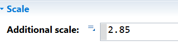
- So if you want your forearm to be 1.5 meters long and your agent in which the robot is located has a scale of 1meter=20 pixels, then AS=1.5*38/20 = 2.85.
You will need to change the default formula
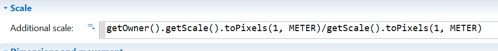 With the additional scale number
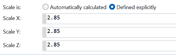
You also need to change the values in the robot presentation. For this, click on the robot presentation, select “scale is defined explicitly” in the “position and size” section of the properties and use the same scale you used in the additional scale value of the robot icon for all 3 scales: scale X, scale Y and scale Z.

Move By Robot Process Block
This is the block you use in order to make the robotic arm operational. You can connect it to any process flow to move normal agents or material items if you are using the material handling library.
Agent Height
Here you can define the height of the agent in order for the robotic arm plug to position itself exactly on the top of the agent. Of course your agent height should be equal to your animation height, otherwise this will not show a correct 3D animation. This value can be fixed for all agents, or it can be dynamic using your agent height parameters if you have created one.
If you have for instance an agent of type Box that has a parameter or variable called height, you would need to do the following:
((Box)agent).height
From the move by robot block perspective, all agents are of type “Agent” so you need to make the transformation from agent to box in order to be able to use the agent’s properties.
Queue Capacity
This block has an embedded queue. This works just as any other block such as a seize, a service, etc. This queue is used to determine what agents can be picked and taken into consideration for priorities.
Has Loading/Unloading Time
You can define if you want the robotic arm to spend some time loading and unloading an object. This is associated to some actions such as “on loading started” and “on loading finished” that are shown if you want to use loading time.
Robot Agent
Here you define the robot object that will be used as a resource to move agents with this process block. You can only choose 1 robot.
Task Priority
This defines from the robot perspective, the priority of the process block with respect to others. If you have 1 robot and 3 move by robot process blocks, the robot will choose to move first the objects in the move by robot process with the highest priority. If all the priorities are the same, it will use FIFO. Note that you cannot choose the priority of agents, the priorities are related only to the process blocks.
Destination
The destination has to be defined by x,y,z coordinates (in pixels), and this is the only way you can define a destination for any object.
Actions – On Enter
You can use this as any other process block, with the difference that you have to specify your agent type, for instance if you have a box agent moving through this block, instead of agent.counter++; you would do:
((Box)agent).counter++;
Release
In this section you can define if the robot stays where it is, or if it goes back to the initial angles.
F.A.Q.
I don’t understand the initial rotation angles?
For all initial rotation angles, zero means no flexion of the joint. So, if all joints are set to zero, the robotic arm will be pointing to the sky. Just try them out and discover by yourself how this works.
I’m getting weird movements with the robot
Make sure you are using the recommended initial angles ranges (see above). Also consider changing the time step when increasing the joints rotation speed in order to have the required precision.
I need help, I can’t figure out how to use this.
Read the documentation carefully. If you want help, we will charge you the hourly rate that you can see at https://www.noorjax.com/ when you scroll down, with a minimum of 1 hour paid in advance. Send us a message if you want help, but do not ask for free help.
Can I use this commercially?
Yes. If you make millions using this robotic arm, and you feel bad about it, send us a message and you can pay us what you feel is right or just use this link https://www.paypal.com/donate/?hosted_button_id=GW77FD5WVVAR8. Contact us before payment if you need an invoice. If you don’t want to pay, then don’t pay. But make sure you help other people in need in the future.
Can I use this Academically?
Make sure to put somewhere in your study that you got our help (acknowledgements are nice). Send us your final research and we will post it somewhere. If you want, you can donate by just paypaling us using this link: https://www.paypal.com/donate/?hosted_button_id=GW77FD5WVVAR8.
The robot is crushing with the objects around it. How can I solve this?
The robot doesn’t have collision detection so you can’t.
I need a new feature
Contact us for a quote.
I want to remove the Noorjax logo from the robotic arm
This cannot be done for free. Contact us for a quote.
The 3D quality could be better
We can actually give you a version with really high quality graphics, but this come at a cost. It takes time for AnyLogic to render the 3D object, so the public version has a bit less quality in order to avoid people complaining about that. We think it’s less likely for people to complain about not perfect quality over rendering time.
When I drag and drop the robot object, the images of the robot don’t show, instead I see weird shapes
You have to use AnyLogic 8.8.5 or later versions for this library to work. If this happens, it means you are using an older version of AnyLogic.
I don’t like your robotic arm
Make one yourself then… it’s not that hard 🙂