Robotic arms have been a game changer in multiple industries, where each year the use of these, in conjunction with automatic operating algorithms and artificial intelligence, gain more strength. Their productivity, safety and low failure rate make them an interesting alternative.
In the modern manufacturing industry, robotic arms have become essential tools in a variety of sectors. The automotive industry, one of the first to adopt this technology, uses them for tasks such as assembly, welding and painting. In the electronics sector, these robots make it easier to assemble tiny components with precision. Food and beverage processors integrate robots for packaging and handling, while the medical sector uses them in precise surgeries. In metallurgy, they are responsible for handling heavy and hot parts. Although the textile industry has traditionally been manual, it is adopting robotic arms for tasks such as cutting fabric.
There are some easy ways to do it
What if we want to make a simulation model that uses a robotic arm in Anylogic? It can be done in many ways, it will depend on the level of precision we require.
Currently AnyLogic does not offer any object in its libraries that represents a robotic arm, however, we can use certain “tricks” to model processes that require it. For instance:
- If on a workstation there is an object that must be welded by a robotic arm, we can simply simulate the robotic arm in a fictitious way, creating a resource pool and specifying a Delay time for that process.
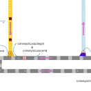
- If a part must be transported by a robotic arm from point A to point B, we can also do it fictitiously, simply by teleporting or moving the object, and using a resource pool to symbolize this arm/resource.
- To transport a piece, it is possible to use the Jib Crane object from the handling material library, in this way we could represent the movement of an object from one point to another, however, it is an approach that is far from reality.
Although it can be “modeled”, all of the previous points have a problem, and that is that in moderately complex models or where a certain degree of precision is required, these approaches to solutions may be far from reality.
There are advanced ways to do it
What is the closest thing to a robotic arm that can be modeled in Anylogic? Well, a robotic arm with its movement patterns. It will only be limited by the imagination and knowledge of the modeler.
Anylogic is a very flexible simulation software, so you can always create new solutions or objects to solve problems, and the creation of a robotic arm is no exception.
Each modeler will have their preferences and ways of solving a problem, however, here we will discuss a way to model a robotic arm:
- We can first divide an arm into different parts:
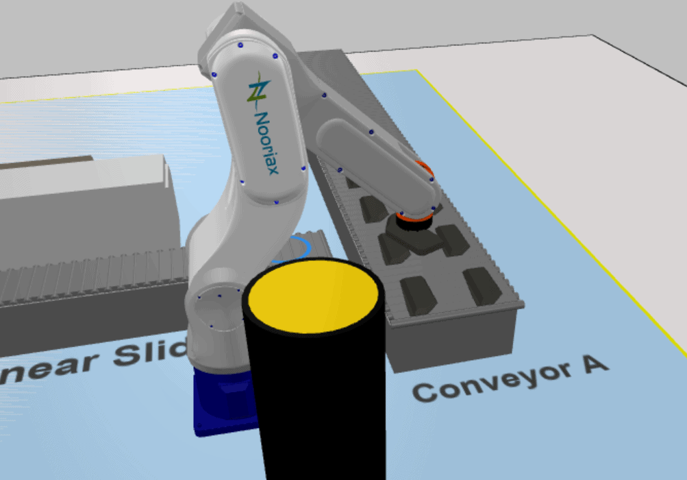
- We will need a 3D object that can serve as an “arm” to visualize this robot during the simulation.
- Each part of the robot can be an agent that lives inside the other, so that the plug lives inside the forearm, the forearm lives inside the upper arm, and so on. In this way, when you rotate or move one part of the robot, the rest will move together.
- Inevitably we will use trigonometry to calculate the angles of each joint of the arm, with the aim of reaching the object that wants to be transported or processed. (that’s why we should have paid attention in the calculus/algebra class).
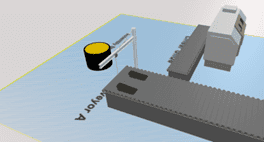
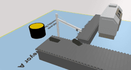
Robotic Arm vs Material Handling Crane
Some differences that we can find between using the material handling library crane and creating a robot on our own are the following:
- The crane has three movements. The rotation, the up and down movement of the object and the trolley speed, which is a horizontal movement. The robot does not have movements of its parts, only rotations around an axis. It has basal rotation (which is the same as that of the crane), a shoulder rotation, an elbow rotation, and a wrist rotation.
- As a result of the previous difference, it appears that we can configure rotation speeds for each of the aforementioned axes, so, instead of defining speeds in m/s as with the crane, we can define rotation speeds in degrees/s. In this way, we can better represent how robots work in reality.
- Another important difference is aesthetics. It is usually interesting for stakeholders that the simulation represents reality as it really is.
For the modeler it can be a key point to verify that the simulation is really doing what it should do, at the correct times and with the correct mechanics. For the end user of the simulation, seeing that a crane is doing what a robot should do can mean rejection or even a factor in not validating the simulation.
But we have the robot for you already, check our free robotic arm here:
https://noorjax.com/2023/11/21/robotic-arm-library/